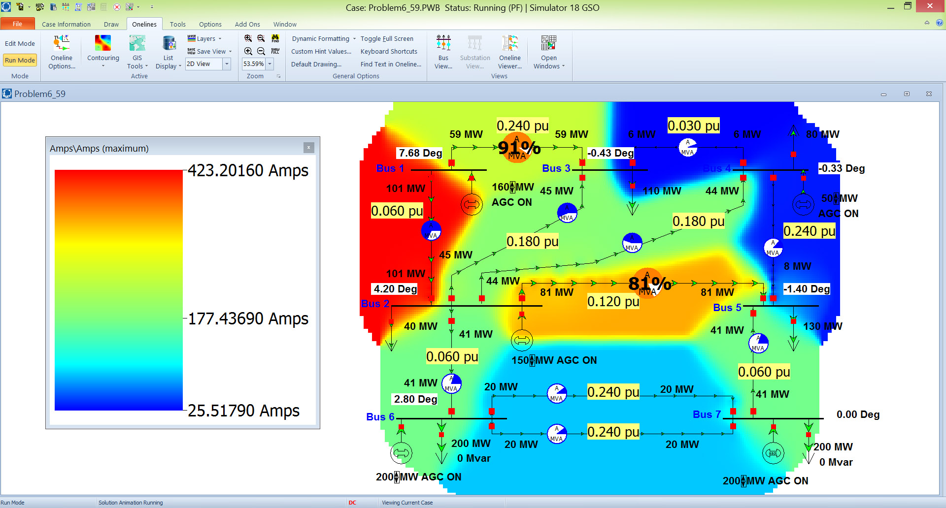

If any of the criteria is violated, you will need to modify your design and redo the analysis until the modified system meet the criteria. Return to base case and increase the load at Bus 12 to 22 MW, 10 MVAR. Is there any line or bus voltage violation, if the line between Bus 3 and Bus 4 is shut down for the maintanence 4. What is the generation at the slack bus? 3. Determine the total load in the system, the losses and the total generation.

Examine the power flow output and verify that the voltages are within the range 0.98-1.06 pu with no overloaded lines or transformers 2.
#Power world simulator power system analysis sorsby generator
Positive, Negative and Zero Sequence Data for All Generators Generator Positive Sequence Negative Sequence (pu) (pu) 0.2 0.1 0.2 0.1 Zero Sequence (pu) 0.01 0.01 0.01 Neutral to Ground Impedance (pu) 0.04 0.04 1 2 3 0.2 0.1 0.04 Part A-Power Flow Analysis a) The Power Flow program will be first used to study the base case design presented in tables. Zero Sequence Data for lines Use the default values provided by Power world on running the Fault Analysis Tool. Assume the system base to be 138kV, 100MVA. Prepeare a nice report to present your results in the desired report format. Model this power system using the Power World Simulation program and perform the power flow and short circuit analysis according to the following instructions. Transcribed image text: The data of a 12-bus power system is given in following tables.


 0 kommentar(er)
